Slicing for Strength: Best Slicer Settings for Functional Parts
Introduction
If you’re printing functional parts—brackets, gears, enclosures, or anything that actually needs to handle stress—you’ve probably had something snap during use. The default slicer profiles that work for decorative prints just don’t cut it when real forces come into play. This guide walks through the Best Slicer Settings for strength, covering wall counts, infill patterns, material-specific tweaks, and the one setting most people overlook entirely: print orientation. Whether you’re a maker, engineer, or just someone trying to print parts that last, this is about getting prints that actually hold up. We’ll hit the key parameters, common mistakes that kill durability, and recommendations for different materials and uses. By the end, you’ll have a practical approach to dialing in your slicer for strength.
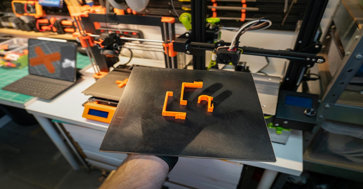 3D Printed bracket showing visible layer lines and thick walls” title=”Functional Bracket with Optimized Wall Thickness” />
Why Strength Settings Matter for Functional Parts
There’s a real difference between a benchy and a bracket. A decorative print can look perfect but fail under minimal load. A functional part—a hook holding a bag, a gear in a drive train, an electronics enclosure—needs to handle load, impact, or heat without catastrophic failure.. For more on this, see our guide on How to Use Meshmixer for 3D Print Preparation and Repair: A Practical Guide.
Bad settings cause real failures. Layer separation under tension, cracks at stress points, parts shattering on impact. I’ve seen people blame their filament or printer when the real problem was a slicer setting that prioritized looks over durability. Tuning these settings is often a more effective upgrade than switching to a premium filament. It’s direct, repeatable, and free.
Ground this in experience: a part failing at the layer line usually isn’t a material problem—it’s a settings problem. Understanding these parameters means you design for reality, not just the slicer preview.
Key Slicer Settings That Directly Impact Strength
Several slicer settings have a disproportionate effect on how a part handles real-world forces. Here’s what matters most:
- Wall Thickness / Perimeters: Often the single most impactful setting. More perimeters create a thicker shell that resists shear and impact. For functional parts, 3 to 4 perimeters is baseline.
- Infill Density & Pattern: Infill provides internal support. While 100% infill is overkill for most cases, the pattern matters as much as the percentage. Gyroid handles stress evenly in all directions, while cubic is excellent for Z-axis loads.
- Layer Height: Thinner layers generally improve interlayer adhesion (good for tensile strength), but thicker layers can be better for compressive loads. It’s a tradeoff between strength type and print time.
- Top / Bottom Layers: Weak top and bottom surfaces create potential failure points, especially when parts are loaded along the Z-axis. Increasing these layers reinforces the part’s weakest direction.
- Print Orientation: Not a numeric setting, but the most powerful lever you have. A part printed flat is much stronger along certain axes than one printed standing upright.
Understanding the why behind each setting matters more than memorizing a single number. Let’s dig deeper into each.
Layer Height vs. Strength: Finding the Right Balance
Common advice says ‘lower layer height equals stronger prints.’ That’s true for tensile strength—the ability to resist being pulled apart. Thinner layers (like 0.12mm) bond more intimately, reducing the weak interlayer junction that leads to cracking under tension.
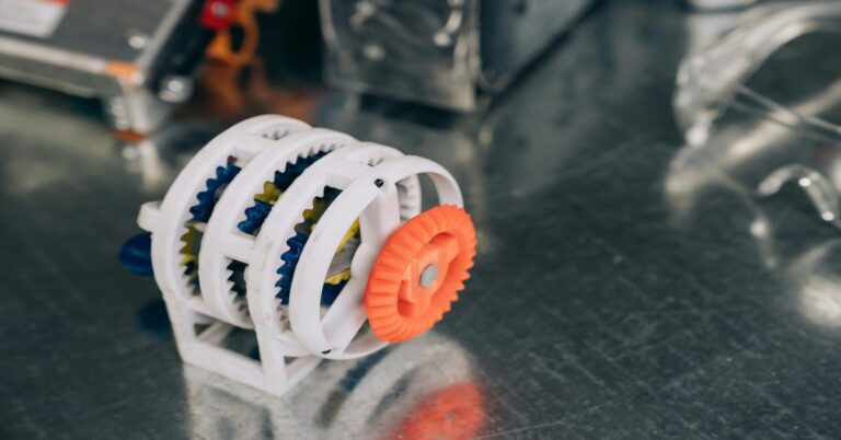
But there’s a catch. Thicker layers (like 0.28mm) can actually be stronger under compressive loads, because each layer is physically larger and can withstand more before buckling. I’ve seen printed gears that should have failed under torque perform fine because they were printed with a 0.28mm layer height, allowing the teeth to resist deformation better than a thinner print.
So which do you choose? For a part under tension (like a handle or hanger), go with a lower layer height. For a part under compression (like a support column or bracket), consider a taller layer. A solid starting point for most functional parts on a 0.4mm nozzle is 0.2mm—it’s a balanced default that works across different load types.
Best Infill Patterns for Durability: Gyroid, Cubic, or Concentric?
Infill isn’t just about filling space—it’s about distributing stress. The pattern determines how effectively your internal structure handles forces. Here’s how the top contenders stack up:
- Gyroid: The champion for even stress distribution. Its wavy, non-linear structure doesn’t create weak points in any direction. Ideal for parts that experience multi-axial loads—think a camera mount or robot arm component. For general functional use, it’s my default.
- Cubic: Shapes like interlocking cubes. Provides excellent Z-axis strength because the diagonal supports transfer load vertically. Great for structural brackets or parts compressed from above.
- Concentric: Very strong along the X-Y axis but weaker in shear and Z. Surprisingly impact-resistant, but can separate under torsional loads. Best for parts that flex or deform, like a living hinge.
- Triangles: Good for vertical loads, similar to cubic but often more rigid. Works for things like shelving brackets.
Infill density sweet spot for functional parts is usually 25–50%. Beyond 50%, the law of diminishing returns kicks in—more plastic doesn’t add proportional strength. For most brackets and enclosures, 30% gyroid is a great starting point.
Wall Thickness and Perimeters: The Backbone of Strength
If you ignore everything else, get this right. The number of perimeters (the walls of your print) is the primary defense against layer separation and impact. A part with 2 walls is a shell; a part with 4 walls is a chassis.
Increasing perimeters from 2 to 4 can do more for durability than doubling infill from 15% to 30%. For thin-walled parts (like a duct or bracket), the wall is literally the structural element. More perimeters create a thicker, stiffer shell that’s much harder to break.
Here’s a practical rule of thumb for a 0.4mm nozzle:. For more on this, see our guide on Fusion 360 vs Blender: Which Software Should You Learn?.
- 2 perimeters: Prototypes, non-critical prints.
- 3 perimeters: Moderate stress, general use.
- 4 perimeters: Functional parts, brackets, hangers.
- 5+ perimeters: High-stress parts, tools, load-bearing components. Creates wall thickness of 2mm or more.
Remember that wall thickness depends on nozzle size. A 0.4mm nozzle with 4 perimeters gives a 1.6mm wall. If you need more, use a 0.6mm or 0.8mm nozzle for thicker walls per perimeter. Upgrading wall count is almost always a better investment than adding infill.

Material-Specific Slicer Tweaks for Maximum Strength
Different filaments respond to slicer settings in unique ways. Here are the key tweaks for common materials:
- PLA: Most forgiving. For strength, print at the high end of the temperature range (215-230°C). This boosts layer adhesion. Consider using more perimeters (4-5) to compensate for PLA’s brittleness. Cooling is generally good, but don’t overdo it right as layers start forming.
- PETG: Hero of functional prints. Biggest mistake is overdrying or cooling too fast. PETG needs slower cooling fan to avoid brittle layers. Start with fan off for first few layers, then use low fan speed (30-40%). Increase hotend temperature (240-260°C) to improve layer fusion. For those new to PETG, a dedicated PETG filament spool makes tuning more predictable.
- ABS/ASA: Heat resistance and toughness. An enclosure is non-negotiable. In your slicer, use a higher extrusion multiplier (105-110%) to ensure good interlayer bonding. Reduce fan speed to almost zero to prevent warping and layer cracks.
- Nylon/PC: Extremely strong but hygroscopic. The setting that matters most is drying. If filament isn’t dry, no setting saves it. Use a dryer box. For strength, use higher temperature (260-290°C) and slightly wider line width (0.45mm on 0.4mm nozzle) to improve layer adhesion.
Top/Bottom Layers and Z-Axis Strength: What Most Guides Miss
The Z-axis is almost always the weakest direction in a 3D printed part. Layer adhesion fails first. Increasing top and bottom layers directly reinforces this weak plane. For functional parts, don’t settle for 3. Go to 5 or 6 top and bottom layers. This creates a denser, more uniform surface that resists pulling forces acting on the vertical axis.
Another tip: set the top/bottom infill pattern to ‘monotonic.’ This ensures infill lines print in the same direction, creating a flatter, more accurate surface. Matters when top or bottom surfaces are part of a mating feature or load path. Don’t let a glossy top fool you—thickness and uniformity count for strength.
Print Orientation: The Most Overlooked Setting
Your slicer’s orientation tool is the most powerful strength enhancer you’re likely overlooking. A part printed flat (largest face down) has layer lines running perpendicular to the bed. The weakest direction—between layers—is along the Z-axis. So if you’re printing a bracket that will be pulled outward, you want the pulling force along X or Y axes, not Z.
Practical example: a horizontal bracket. Print it standing upright, layer lines are vertical. Put weight on it, you’re pulling those layers apart (weak). Print it flat on the bed, layer lines are horizontal, weight supported by continuous loops of your perimeters (strong).
Use the ‘Put Face on Bed’ tool in your slicer to reorient parts. Might require more support material, but for a functional part, strength gain is worth it. Orientation trumps infill percentage for specific load types.
Common Mistakes That Weaken Your Prints
Even with right settings, simple oversights can ruin strength. Here’s what to watch for:
- Too low infill density: 10% infill works for a planter. Not for a bracket. 25% is absolute minimum for functional parts.
- Ignoring cooling for PETG: Crank the fan and you get brittle, crumbly parts. Always start low.
- Too few perimeters for thin parts: Single-wall print will never be strong. If your part is thin, use 4-5 perimeters to turn entire print into a solid wall.
- Wrong orientation for load direction: We covered this. Reorient in slicer, not in your head.
- Default bridging settings causing weak spots: Long bridges with default speed create sagging, weak layer lines. Increase bridge fan speed or add support for overhangs on load-bearing areas.
- Skipping temperature towers: Every spool is different. Printing too cold for your specific batch is the easiest way to get weak layer adhesion. Run a tower for any new material.
Recommended Slicer Profiles for Common Use Cases
These are starting points, not rigid formulas. Test and adapt. Here are three profiles tuned for specific functional scenarios:
Profile 1: High-Strength General Part (PLA)
- Material: PLA
- Layer Height: 0.2mm
- Perimeters: 4
- Infill: 30% Gyroid
- Top/Bottom Layers: 5
- Why this works: 4 perimeters build a strong shell, gyroid infill handles multi-directional stress. Robust profile for brackets, clips, enclosures.
Profile 2: Impact-Resistant Part (PETG)
- Material: PETG
- Layer Height: 0.24mm
- Perimeters: 3
- Infill: 40% Cubic
- Cooling: 30% fan speed (after initial 3 layers)
- Why this works: Thicker layers and cubic infill create stiff internal structure that resists impact. Lower fan speed prevents embrittlement.
Profile 3: Thin-Walled Structural Part (e.g., Bracket)
- Material: Any (PLA or PETG depending on temperature needs)
- Layer Height: 0.2mm
- Perimeters: 5
- Infill: 25% Gyroid
- Top/Bottom Layers: 6
- Why this works: 5 perimeters make thin-walled part effectively solid. 25% infill provides slight internal structure, but walls do the heavy lifting. Top/bottom layers reinforce weakest Z-axis.
Tools and Accessories to Improve Print Strength
Settings get you 90% of the way. The right gear handles the last 10%.
- Digital Calipers: If you’re tuning perimeters or infill, you need to measure actual wall thickness. A digital caliper lets you verify settings and ensure consistency.
- Build Surface Adhesion Aids: A part that lifts mid-print is a weak part. A quality PEI bed sheet makes adhesion reliable. For ABS or PETG, a glue stick or Magigoo prevents warping that ruins layer bonding.
- Filament Dryer: For hygroscopic materials like PETG, Nylon, PC, moisture is the enemy. A dryer prevents zits, bubbles, and cracks at the layer line. Non-negotiable for strong functional parts.
- Enclosure Kit for Engineering Materials: ABS, ASA, PC need a stable, warm environment. An enclosure kit prevents drafts that cause layer separation. Unlocks full strength of these materials.
If you’re struggling with layer adhesion or inconsistent strength despite good settings, a quality dryer or enclosure kit is your next best investment.

Final Thoughts: Dialing In Settings for Your Needs
Core takeaway: prioritize your walls, choose your infill pattern with purpose, and always consider orientation. The best slicer settings for strength depend on what you’re printing—a bracket needs different specs than a handle. Start with a robust general profile (like the PLA one above) and tune from there. Test your parts. Run a bend test or stress test. The parts that survive are built with understanding, not just a configuration. Pick the profile that matches your part’s real-world demands and start printing with confidence. For any gear that makes dialing in easier, the tools section has you covered.
At the end of the day, the right choice is the one you’ll actually use. I’d rather see someone produce a hundred simple prints with basic software than quit in frustration because they jumped into something too complex. Start simple, build skills, and expand from there.. For more on this, see our guide on Best Free STL Files: Top Sites for Downloading 3D Models.
best slicer settings for strength depend on what you’re printing